 |
Table of Contents
Executive Summary Introduction Mobile Platform Actuators |
|
|
Table of Contents
Executive Summary Introduction Mobile Platform Actuators |
The color senor arm provides a means of looking and detecting colors
in different locations around the robot. The arm uses a spring and two
bump switches to protect the servo that drives it. This design could also
be used to detect obstacles.
The tile grabber provides a means of detecting tiles and a way of holding them in place. Because the tiles are too light to be detected by any other means, the tile grabber presses down onto the tile thus sensing it's presences. The tile grabber also has a sensor that detects when a tile is in position and is ready to be moved and placed.
I wanted to build a robot that manipulated its environment in a constructive
manner. After evaluating many ideas including a sand painting robot and
one that would make mosaics out of M&M's, I decided tiles would be
the easiest medium to implement and clean up. This idea had been done before
by Alan Senior with his robot, TileBot. Senior's robot dispensed tiles
which meant it had to be reloaded. Also, it placed thin black plastic 'tiles'
which limited TileBot to creating only black and white images. I wanted
to build a robot that could find and identify colored tiles in it's environment
and then arrange them to create images. Due to time constraints and unforseen
difficulties, I was only able to complete the first part.
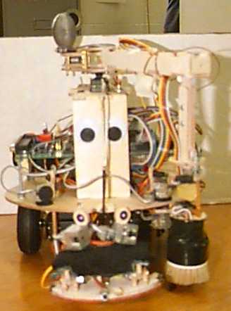
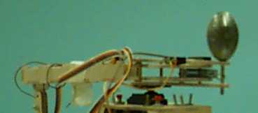
Lothar consists of a color sensor on a rotating arm and a tile grabber supported by a 1/8 inch plywood structure propelled by two hacked servos. Lothar's processing power is provided by a Motorola HC11 EVBU board expanded with 32k of RAM, a clock divider to provide a 40 kHz signal, two memory mapped output ports, two memory mapped input ports, and a multiplexed analog port.
This paper is a description of Lothar's mobile platform, actuators, and sensors which are each discussed in detail in the following sections.
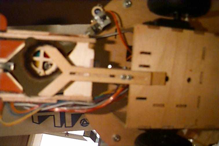
The physical structure of the mobile platform consists of an open-ended box which houses the primary battery pack, the two drive servos, and the grabber servo. The two circuit boards and the color turret tower are attached to the main chasse or top of the box. A V-shaped tile jaw is attached on the bottom front for pushing and positioning tiles. I had to remove a barrier that enclosed the batteries when I started using six C batteries instead of the originally designed for six AA batteries. I added a secondary six pack of AA batteries that had to be taped onto the main chasse due to the lack of space in the battery compartment. I also had great difficulty accessing the two circuit boards because the color turret made it necessary to stack them.
Movement is provided by two partially hacked 45 inch/ounce servos with three inch wheels attached. These servos are positioned close to the front for greater control of the jaw. There is also a closed-ended nut glued to the rear to provide a pivot for dragging the rear end. This drive system was not very accurate or responsive primarily because the servos I used were of very low quality and the refresh rate needed by the servo was too slow. In retrospect, I should have used geared stepper motors.
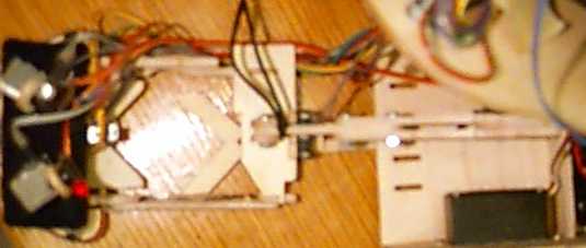
The tile-gripping assembly enables Lothar to sense and grip tiles. The gripper is actuated by a 45 inch/ounce servo mounted above the left drive servo. The gripper is pulled up by a rubber band so that its at rest in the open position when the servo is not activated. The gripper consists of four parts: the major armature, the ankle, two minor armatures, and the foot. The servo is
attached to the major armature which is then connected to the ankle.
The ankle has a limit switch attached that comes in contact with the ram
when the grabber is closed and there are no tiles under the foot. Due to
their light weight, impact with tiles can not be detected and this is the
only way to detect them. The ankle is connected to the foot by the two
minor armatures. The foot contains a limit switch that makes contact if
a tile is properly in position against the tile jaw. The foot also has
three bump switches and two IR sensors for obstacle avoidance. The under
side of the foot is covered in rubber for grabbing tiles that are not yet
fully in position.
Gripper from above |
Gripper from below |
 |
 |
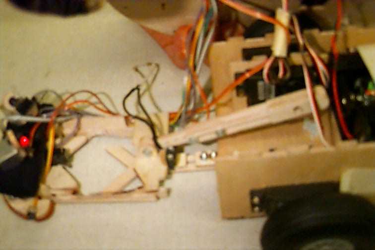
The color sensor turret arm moves and supports the color sensor, allowing Lothar to determine the color of tiles in the V-shaped jaw as well as finding and following colored trails. It consists of a 45 inch/ounce servo, a pivot housing, and a 12 inch arm. The purpose of the pivot housing is to protect the servo from stripping gears by providing a spring to absorb impact. The pivot housing is a pair of identical 1/8 inch plywood supports that are spaced ½ inch apart by 1/8 inch brass rod. A spring and a counter balance are attached to the brass spacing rod farthest from where the servo is mounted. The brass spacer closest to where the servo is mounted serves as a pivot for the arm which is also attached to the other end of the spring. Two limit switches are mounted to the arm and make contact when force is applied to the arm. This also aids in protecting the servo.
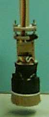
The incandescent lamp was used instead of LEDs because the light it
produces covers more of the visible spectrum than can be expected from
LEDs. After trying a small 6 volt 25 milliamp light, I decided that a larger
lamp was needed and implemented a 6 volt 100 milliamp light. Due to the
greater power requirement, a simple driver circuit consisting of a P2N2222
transistor and a 330 ohm resister which can be seen on the right in Figure
1 was also added. This lamp provides enough light to allow the sensors
to read the color of the tiles but being incandescent, it requires more
than .3 seconds to reach full luminescence. This requires that the lamp
stay on or have a warm-up period more than .3 seconds each time the light
is turned on.
Three CDS are used to sense the amount of light reflected off of a tile and filtered through three different color filters. A CDS cell is a solid state device which increases conductivity when light is present. Using this fact, I constructed three voltage divider circuits using 10 k potentiometers as seen on the left of Figure 1. The signal is then converted from analog to digital using PE1, PE2, and PE3 on the HC11. My concerns about inconsistent readings from these sensors where quieted by how consistent the experimental data was.
The selection of the color filters or jells as they are called in the
lighting industry was very important and challenging. Instead of choosing
three from the 159 filters that would best enable Lothar to distinguish
the tiles, I chose eight. I designed my sensor so that the jells could
be mounted to wheels and these wheels could be changed rather easily. Three
wheels where constructed and tested on each tile color. The table below
shows which jells where used on which wheel.
| Wheel | Position | Color/Name | Y(%) | Part Number |
| 0 | 1 | Yellow | 80.00 | #139 |
| 2 | True Red | 6.87 | #109 | |
| 3 | Just Blue | 5.93 | #79 | |
| 1 | 1 | Primary Green | 14.97 | #139 |
| 2 | Pail Blue | 54.39 | #63 | |
| 3 | Flame Red | 17.97 | #164 | |
| 2 | 1 | Yellow | 80.00 | #101 |
| 2 | Magenta | 10.92 | #113 | |
| 3 | Marine Blue | 41.32 | #131 |
The mechanical structure consists of five disks held together by screws
and the circuit board. Two of the disks combine to form the wheels previously
mentioned. Two other disks are used to hold the circuit board in place
and the last supports the lamp. Paint brush bristles where wrapped around
this frame blocking out light from outside.
The test consisted of using each of the three wheels described in Table 1 on all of the tiles. A minium of 45 readings where taken for every wheel and tile combination. The test software warmed up the sensor and took five readings (one from each CDS cells) and waited for input on the keyboard. The software would then loop, waiting for input and then receive five readings. To provide variance, I picked up and set the sensor down again between every five readings. Below are some charts and tables describing the test results.
After inspecting the data, I chose to use wheel two because it provided the greatest distribution for each of the sensors. This sensor works well but there are some important changes I would have liked to make. The sensors are too spread out and this means that they need at least one square inch of color to identify it. The light shines mainly on the area seen by sensors one and three, leaving sensor two in the dark. The senor needs to be about 3/8 inches from the ground to look at tiles and on the ground to best identify colors on the ground.
More details avialable in the Final Report, lothar.pdf
I feel that using cheep servos instead of geared stepper motors was a mistake. I chose to use servos because they did not require driving circuitry, but their poor performance far out weighed there ease on implementation. I would also like to greatly reduce the size of the color sensors and use multiple color sensors instead of the arm. I believe I could get the sensor down to the size of a dime and reduce the power requirement by 150%. I learned a great deal this summer, unfortunately much of what I learned did not make it onto Lothar, there simple was not enough time.